Exhaust Fan Interlock Wiring Diagram
Interlock wiring diagram for exhaust fan and cooking equipment. I was asked to interlock a make up air system in a restaurant.
Exhaust Fan Interlock Wiring Diagram easywiring

Wiring diagrams are shown on pages n.
Exhaust fan interlock wiring diagram. This is easy to do when the fan starter is in the auto position, the control system can power the damper actuator, and a damper end switch will close the. Wiring diagrams are provided with all fans. Provide the following operational and interlock functions when the exhaust system is.
Does anyone have a wiring diagram? Turning on any piece of cooking equipment under a hood will turn on the exhaust fan for that hood. On some newer homes i've seen there is a switch in the hallway, that somehow is wired in with the fan and furnace.
The wiring diagram will be specific to that. Electrical wiring and connections should be done in accordance with local ordinances and the national Test the upper and lower door interlock switches, cook relay and.
How do i determine what is the principal exhaust fan? What i did was run 14/3 from fan switch box to a central switch, then a 14/2 to a relay box to run the furnace. You need a 3 way switch for the exhaust fan 2 way for the ventilation switch.
The interlock monitor switch will immediately cause the oven fuse to blow if the door is opened and the primary door interlock switch and/or the secondary interlock switch contacts fail in a closed position. I'm thinking i would need a 3 way switch at the bathroom fan. Basically when the lab hood exhaust fan turns on the outside air unit needs to turn on via an interlocking mechanism.
Leave the existing black connected. I have a belimo 2 position actuator for outside air dampers and i have a small in in line fan and they are going to install an electric heater package. All fans must be earthed in accordance with as/nzs3000:2007 and local supply regulations.
Connect the power (black) to one lead of the timer and the black fan wire to the remaining timer lead. These systems are designed to control, activate, and operate the exhaust fan(s), supply fan(s), core system(s), and wash system dependent on the hmi settings and temperature sensors. As contactor m1 energies, it’s all normally close (nc) links open and the other normally open (no) links used in the circuit close.
Provide the following for exhaust fan systems. After wiring is complete with supply power switched on and the cop activation run terminals c1 & c2 closed with a switch or jumper, the exhaust fan will run. Wiring wiring must be in accordance with as/nzs3000:2007 and local supply regulations.
I thought i would some how interlock these devices with the hood exhaust system, but i'm not sure how to tie this altogether. He is wanting to put new outside air units in the building and interlock them with some existing fume hood exhaust fans. The equipment is old so there is no type of control system.
Replace a blown fuse w th a 20 ampere class h fuse only. What is the correct way to wire the fan and furnace in a new home. And motor m1 starts to run.
Eie150 diagram er11 m 1~ ln e. Do i have to interlock all the bathroom fans with the furnace. Verify input power voltage before connecting to starters or contactors.
Trs wiring diagram headphone stereo headphones wire. Equipment, follow the interlock test procedure outlined within the cic1 installation instructions. I tried searching but didn't find much.
The activation of the exhaust fan shall occur through an interlock with the cooking appliances, by means of heat sensors [emphasis added] or by means of other approved methods. Exhaust fan interlock wiring diagram. I had to have a set of rca to xlrs specially made up by mark grant i had to send him a copy of the wiring diagram and he told me that it was not the conventional method for wiring a rca to xlr cable barco g808s lumagen hdp isf oppo970hd toshiba ep35 tag av32rdp 4 atc t16s atc c4ca svs pb12 2plus2 xbox360 7.
If the ansul system should discharge. The fan should operate and maintain the factory set To correct rotation of fans reverse any two leads from the 3 phase starter to the fan.
Turning off the last pi\ce of cooking equipment under a hood will turn off the exhaust fan for that hood. Appliance wiring material is a classification of underwriters laboratories inc covering insulated wire and cable intended for internal wiring of appliances and equipment. The system can have up to two zones that the fans are assigned to.
Run a new cable (2 wire) from the 3 way switch box to the fan and connect only the black. Check rotation of fans, exhaust fans will move some air in reverse (see rotation arrow on fan). In alberta you have to interlock the primary exhaust with the furnace.
Afcs wiring diagram list the proper phase, voltage, and amp load. Connect this black to the red in the switch box.
Physical features of a P3 laboratory; DIdoor interlock, ACair... Download Scientific Diagram

I need a wiring diagram for a commercial kitchen vent hood

HVACQuick How To's Starting a booster fan with a current switch from
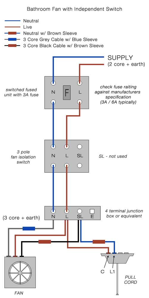
Connecting a Timed Fan Unit How to Wire a Bathroom Extractor Fan with Timer DIY Doctor
Exhaust Fan Interlock Wiring Diagram

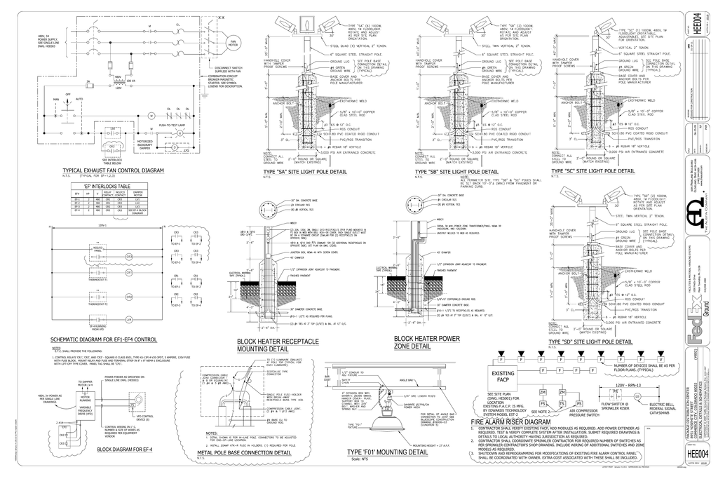
TYPICAL EXHAUST FAN CONTROL DIAGRAM SCHEMATIC
Patent US5433377 Interlock and forced air furnace and HRV Google Patents

Furnace interlock, Alberta Electrician Talk Professional Electrical Contractors Forum

[DIAGRAM] Hampton Bay Ceiling Fans 3 Speed Wiring Diagram 117 391 FULL Version HD Quality 117

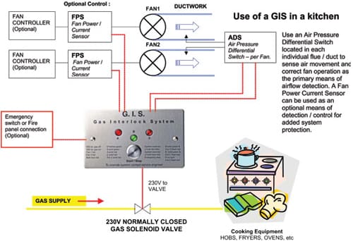
Gas Interlock System R and B Mechanical and Electrical
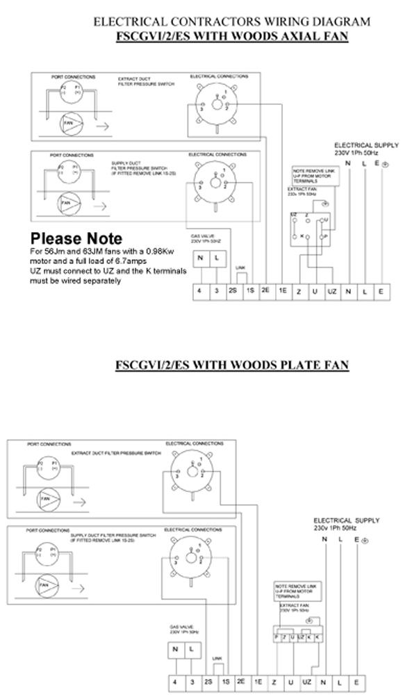
NCSP Gas Ventilation Interlock Panel / NFAN Supply & Stock Extractor Fans & Ventilation
Exhaust Fan Interlock Wiring Diagram

Exhaust Fan Interlock Wiring Diagram

HVACQuick How To's Wiring 1 fan serving 2 baths with 1 switch per bath (with lights) from
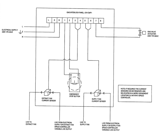
GV1 Gas Ventilation Interlock Panel / NFAN Supply & Stock Extractor Fans & Ventilation
HVACQuick How To's Wiring 1 fan serving 2 baths with 1 switch per bath (with lights) from
Exhaust Fan Interlock Wiring Diagram

starter/ex. fan/damper/gen/bas Electrician Talk Professional Electrical Contractors

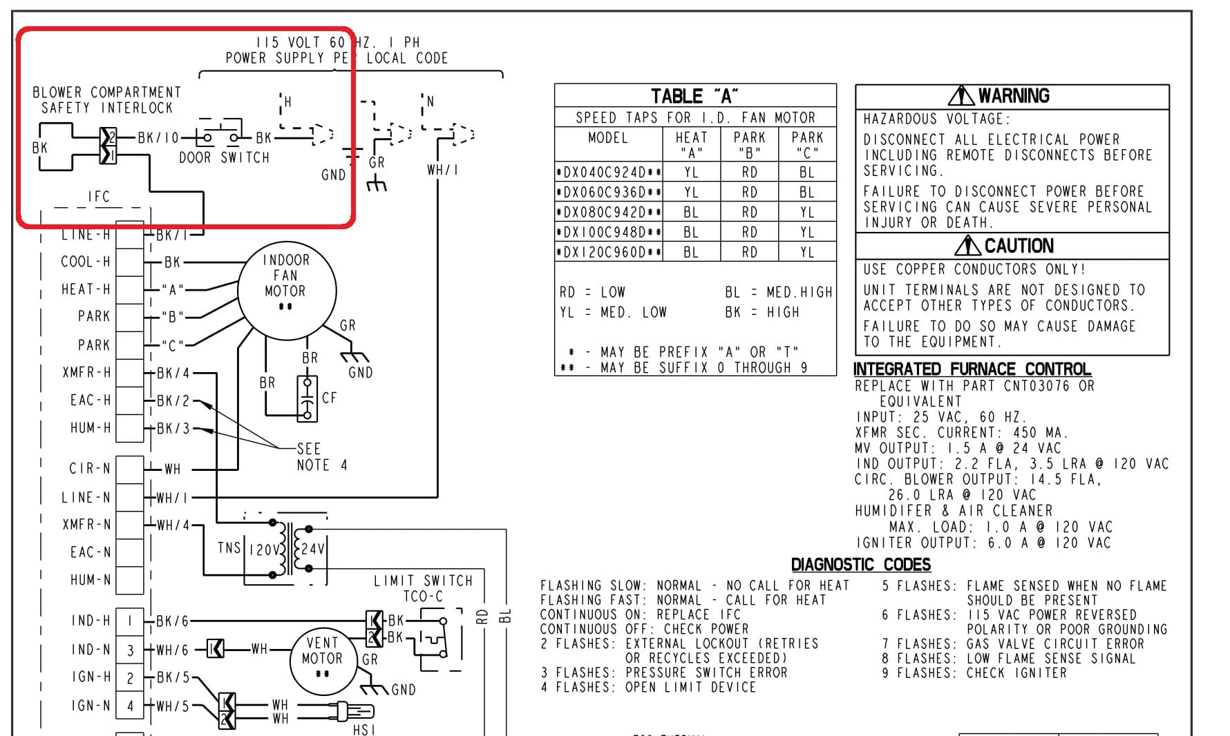
Blower Door Safety Interlock Switch installation, wiring, repair