Single Phase Starter Wiring Diagram
September 8, 2021 on single phase motor wiring diagram with capacitor. This procedure works for electric motors that are able to operate with either 110 or 220 volt power by changing a few […]
Draw A Labelled Circuit Diagram Of Capacitor Start Single
Single phase power is typically reserved for lower power requirements, however in some cases powering a small motor with single phase input power is practical.

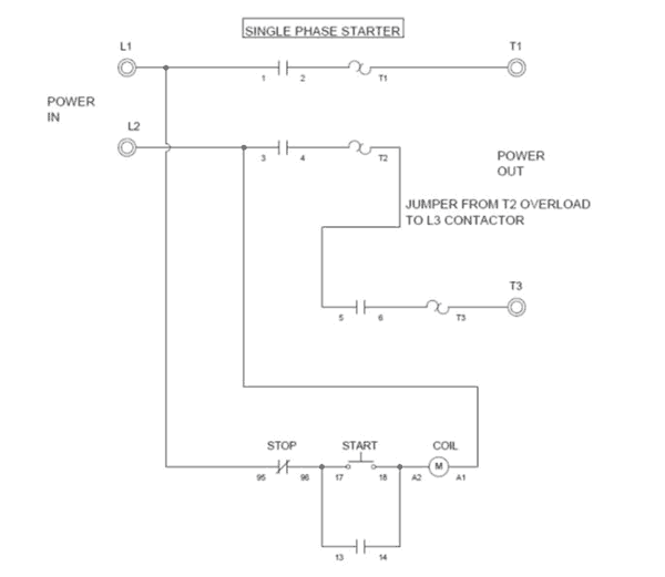
Single phase starter wiring diagram. And the power circuit (thick wire lines) which uses a double pole single throw relay (rmain) and a double pole double throw relay (rdir). Many people can read and understand schematics generally known as label or line diagrams. Split phase permanently connected capacitor.
A wiring diagram usually gives opinion practically the relative point of view and arrangement of. A circuit is usually composed by many components. Razor electric scooter wiring diagram also contactor relay.
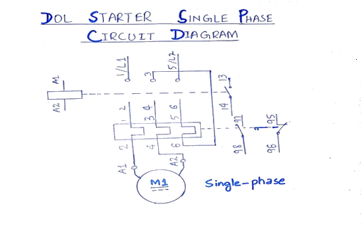
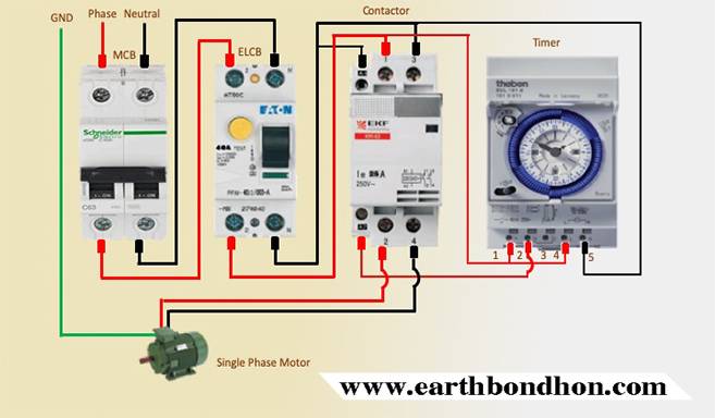
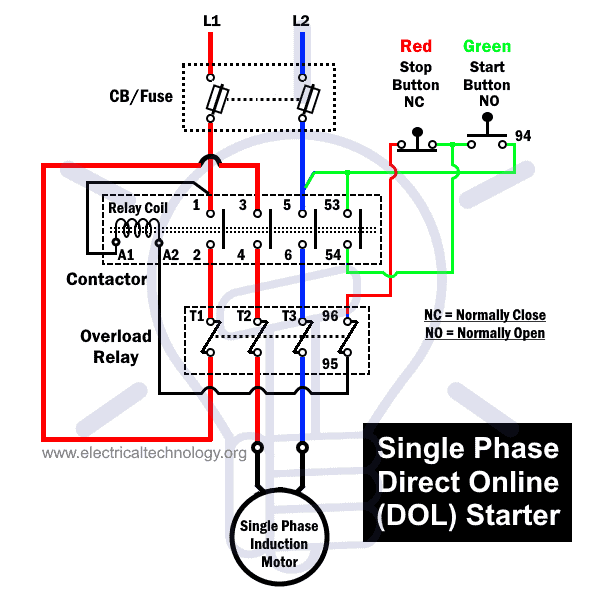
Dol starter wiring connection for single phase motor you. Single phase motor wiring with contactor diagram. It uses a contactor, an overload relay, one auxiliary contact block, a normally open start pushbutton, a normally closed stop pushbutton, and a power supply with a fuse.
1 phase motor starter wiring diagram. Dosto maine aapse share kiya ki aap single phase submersible motor starter ka wiring diagram kaisa hota haiy kaise aap starter bana sakte haiy ummid haiy ki. The first component is symbol that indicate electrical element in the circuit.
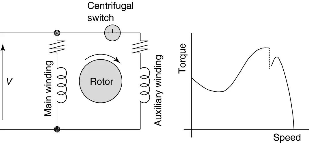
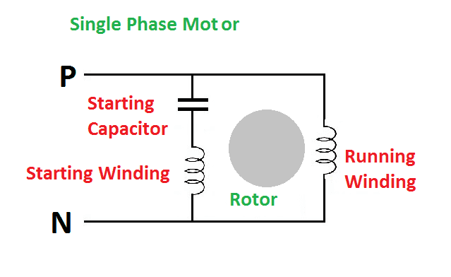
It usually shows how to wire the motor for common configurations such as 110 to 125 volts or 220 to 250 volts and occasionally 208 volts. A 208v single phase water heater is connected to hot 1 and hot 2 plus ground wire. Learn how a capacitor start induction run motor is capable of producing twice as much torque of a split phase motor.
These instructions will probably be easy to comprehend and implement. Product connect a jumper between the h2 and h3 terminals and bring the v in on h1 h4. How to connect single phase motor.
Single phase wiring diagram for hp pumps with governor switch: It uses a single pole double throw type transfer switch to impress a high voltage across the capacitor during start up. Phase wiring diagram today wiring diagram 3 phase to single phase wiring diagram wiring diagram contains several comprehensive illustrations that display the link of assorted products.
Another split phase capacitor run. Baldor single phase 230v motor wiring diagram. Wiring diagram for capacitor start motor techunick biz capacitors motor pioneer radio.
L1 and l2 are designated as the two connection points representing the two electricity flow path inherent with single phase circuits where a single phase supply voltage is fed to the motors internal circuit. Symbols that represent the components of a circuit and lines that represent the connections between them. The other thing that you will get a circuit diagram would be traces.
Wiring diagrams help technicians to see what sort of controls are wired to the system. But, it doesn’t imply link between the wires. For most shore facility applications this is the case.
Ac blower motor wiring diagram furthermore 3 phase star Reversing starter circuit for single phase induction motors updated 1 st september 2008 most single phase electric motors fitted to machine tools, compressors etc. Stop start wiring diagram for air compressor with overload.
Please download these single phase motor starter wiring diagram pdf by using the download button, or right select selected image, then use save image menu. The start and stop circuits could alternatively be controlled using a plc. A three phase motor must be wired based on the diagram on the faceplate.
Injunction of 2 wires is usually indicated by black dot to the junction of two lines. Motor starter schematic and wiring diagram. Collection of single phase motor starter wiring diagram.
The basic diagram view a shows a circle with two leads labeled t1 and t2. Single phase motor wiring diagram with capacitor start capacitor run. Motor forward reverse wiring diagram elec eng world.
Single phase submersible pump starter wiring diagram now if you did not know about the star, run and common wire in your pump motor then follow the below compressor terminals identifying tutorial and same. Wiring diagram not just offers in depth illustrations of whatever you can do, but additionally the processes you should stick to although carrying out so. There’ll be primary lines which are represented by l1, l2, l3, and so on.
Split phase single value capacitor (dual. As stated earlier, the lines in a 240 volt single phase wiring diagram signifies wires. Dol starter wiring connection for single phase starter connections you dol starter connection single phase wiring a single phase motor through 3.
Sometimes, the wires will cross. Internal wiring diagrams of small and fractional horsepower electric motors. Single phase wiring diagram with governor switch:
Split phase capacitor run induction (reversible) reactor start. There are two things which are going to be present in any single phase motor wiring diagram with capacitor. We have to use all 3 poles of the overload relay otherwise the imbalance due to the current flow in only 2 of them will cause unnecessary tripping.
Single Phase Motor Starter Wiring Diagram Elec Eng World

Baldor Single Phase 230v Motor Wiring Diagram easywiring

single phase motor starter circuit diagram Wiring Diagram

how to connect single phase starter DHNX Wiring Diagram
Single Phase Compressor Wiring Diagram Database Wiring

Single Phase Motor Starter Wiring Diagram Database

wiring diagram induction motor single phase Wiring Diagram
Motor Wiring Diagram Wiring Tech

how to connect single phase starter DHNX Wiring Diagram
Dol Starter Wiring Diagram For 3 Phase Wiring Diagram Line
Single Phase Motor Wiring Diagram With Capacitor Start

how to connect single phase starter DHNX Wiring Diagram
Single Phase Submersible Pump Starter Wiring Diagram

Single Phase Motor Starter Wiring Diagram Database
Single Phase Submersible Pump Starter Wiring Diagram

wiring diagram induction motor single phase Wiring Diagram

cima single phase asynchronous motor wiring diagram

single phase motor wiring diagram with capacitor start
Dol Starter Wiring Diagram For 3 Phase Wiring Diagram Line